

API 672 Centrifugal Air Compressor Working Principle Explained
2026-07-19
Centrifugal air compressors built to the API 672 standard are the backbone of critical industrial processes, yet their inner workings often remain a mystery. Ever wondered how these machines achieve reliable, oil-free air at massive scales? At Seize Air, we believe understanding the principle is the first step to mastering performance. In this post, we strip away the complexity and walk you through the core working principle of an API 672 centrifugal air compressor, from impeller aerodynamics to intercooling stages, so you can see exactly what sets these industrial giants apart.
How Inlet Guide Vanes Set the Stage for Efficient Compression
Inlet guide vanes (IGVs) might not steal the spotlight, but they quietly transform how a compressor breathes. Positioned right at the intake, they adjust the swirl and flow angle of incoming air, essentially pre-conditioning it before it meets the impeller. This simple mechanical tweak means the compressor doesn't have to work as hard to grab and squeeze the air, especially when operating away from its design sweet spot. By smoothing out the approach, IGVs cut down on wasteful turbulence and allow the machine to hold onto higher efficiency across a broader load range.
What makes this so effective is how the vanes reshape the velocity triangle at the impeller eye. Adding a measured amount of pre-rotation reduces the relative speed between the blades and the air, which directly lowers shock losses and keeps flow attached under tricky low-flow conditions. It’s a bit like setting the right entry speed on a curved ramp—go in too fast or at the wrong angle, and you skid; get it right, and you glide through. This aerodynamic finesse lets the compressor stage build pressure with less energy, delaying surge and flattening the efficiency curve over the operating envelope.
Today’s systems pair IGVs with responsive actuators and controls that read the process in real time. Whether it’s a gas turbine chasing part-load fuel savings or an industrial blower adapting to demand swings, the vanes move in unison to keep the inflow just right. That constant fine-tuning doesn’t just save kilowatts—it also keeps the equipment clear of damaging stall cycles, boosting long-term reliability. Ultimately, efficient compression isn’t about brute force; it’s about smartly choreographing the air before the real work begins.
The Impeller-Diffuser Duo: Converting Kinetic Energy into Pressure
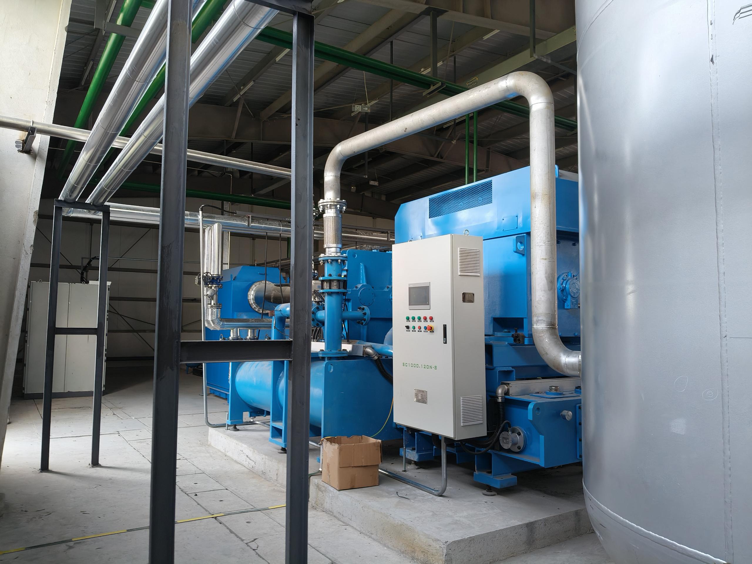
Picture a spinning impeller flinging fluid outward at high speed—that's pure kinetic energy in motion. But raw velocity alone isn't what most systems need; they crave steady, usable pressure. This is where the diffuser steps in, catching that fast-moving flow and cleverly trading speed for force. As the fluid rushes through widening passages, its pace slows, and pressure builds—a simple yet elegant transformation that sits at the heart of countless pumps and compressors. Without this pair, we'd be stuck with a lot of splash and very little push.
The magic lies in how seamlessly these two components collaborate. The impeller does the heavy lifting of acceleration, but the diffuser shapes the outcome, turning chaotic movement into something orderly and powerful. Think of it as a dance: the impeller leads with a burst of energy, and the diffuser follows, guiding that energy into a crescendo of pressure. This synergy isn't just physics—it's a design philosophy that balances speed, geometry, and flow to suit everything from water pumps to jet engines.
Yet getting this duo right demands a careful ear to the ground. Real-world fluids misbehave—swirling, stalling, or losing efficiency when the match isn't perfect. Engineers obsess over blade angles, passage widths, and the subtle interplay between rotation and diffusion. A slight tweak can mean the difference between a whisper-quiet pump and one that vibrates like a jackhammer. That's the challenge that keeps the impeller-diffuser pair endlessly fascinating: nailing the conversion without letting energy slip through the cracks.
Navigating Multi-Stage Configurations for Optimal Discharge Pressures
Achieving the right discharge pressure in a multi-stage pump system isn't simply about stacking stages—it’s a careful balance of hydraulic design, impeller selection, and operating conditions. Each stage contributes incrementally, but the interplay between velocity head, friction losses, and the inherent pressure limitations of each component demands a tailored approach. Overlooking one variable often leads to inefficiencies or premature wear, making a holistic view essential from the outset.
Engineers often find that the sweet spot emerges only after iterative tweaks: adjusting impeller diameters, tweaking diffuser angles, or even rearranging stage sequencing to smooth out pressure pulsations. Real-world factors like fluid temperature, viscosity, and entrained gases can shift the ideal configuration, so simulations must be validated against field data. It’s this back-and-forth—between modeling and actual performance—that separates a workable setup from an optimized one.
Maintenance teams know that even a perfectly configured multi-stage unit will drift over time. Seal clearances widen, impellers erode, and process demands evolve. That’s why periodic re-evaluation of the pressure profile across stages is critical—catching a gradual drop in interstage pressure early can prevent cascading failures. In the end, navigating these configurations is less about a one-time fix and more about building adaptability into the system’s operational DNA.
Why Seal Systems Are Critical in API 672 Compressors
In API 672 compressors handling high-pressure or hazardous gases, seal systems act as the first and often only barrier against leakage that could lead to catastrophic failures. Unlike general industrial compressors, these machines frequently process flammable, toxic, or environmentally sensitive fluids where even minor emissions are unacceptable. The seal's ability to maintain containment under fluctuating pressures, startups, and shutdowns directly determines plant safety and regulatory compliance. A well-designed seal system isn't just a component—it's a safeguard that protects personnel, assets, and the surrounding community.
Reliability of the entire compression train hinges on seal performance, as seal failures are among the leading causes of unscheduled downtime. API 672 explicitly addresses this by defining stringent requirements for seal supply systems, including filtration, temperature control, and leakage monitoring. For instance, dry gas seals require ultra-clean barrier gas to prevent face contamination, while liquid film seals may demand elaborate overhead tanks and degassing loops. Ignoring these details invites frequent trips, excessive maintenance, and the risk of process gas contamination that can ruin downstream catalyst beds or product quality.
Beyond immediate safety and uptime, seal systems profoundly influence long-term operating economics. Energy losses from excessive seal leakage or poorly designed buffer gas consumption can silently erode margins, especially in large compressors running continuously. Modern seal designs with optimized clearances and advanced materials reduce power draw and extend service intervals, but only when matched to the specific gas composition and operating envelope. True resiliency comes from treating the seal system not as an afterthought, but as an integral part of the compressor's lifecycle strategy—one that pays dividends through lower emissions, reduced maintenance, and unwavering process security.
Cooling Strategies to Manage Heat of Compression
Managing the heat released when compressing gases isn't just about slapping on a bigger fan. It starts with rethinking the compression itself. Multi-stage compression with intercooling breaks the process into manageable chunks, pulling excess heat out between stages. This lowers the overall temperature leap and reduces the energy demand on downstream cooling systems. Pairing that with efficient compressor designs—like optimized blade profiles or liquid-injected screw compressors—can absorb heat right at the source, minimizing the thermal load before it spreads through the system.
Beyond the compressor, the choice of cooling medium and how you use it shapes everything. Closed-loop chilled water systems offer tight temperature control but need careful energy balancing to avoid becoming a heat source themselves. Evaporative cooling, when the climate allows, can slash water consumption while maintaining performance. Some plants are now integrating waste heat recovery, directing compressed heat into facility heating or process preheating, turning a thermal headache into a usable asset. The key is blending the cooling approach with the specific operating conditions rather than treating it as a generic bolt-on.
Finally, the way you monitor and adapt makes or breaks the strategy. Real-time thermal imaging and embedded sensors let you spot hot zones before they become failures. Variable speed drives on cooling fans and pumps adjust to actual load, slashing energy waste during partial capacity. It's about building a responsive envelope around the entire compression train, not just one component. When the cooling system learns from the compressor’s rhythm, you stop fighting the heat and start directing it.
Real-World Performance: Surge, Choke, and Operating Range
In real-world compressor operations, surge and choke define the absolute boundaries of viable performance. Surge, a violent flow reversal triggered by excessive pressure rise at low flow rates, can destroy bearings and seals within seconds. It’s not a gradual drop in efficiency—it’s a catastrophic instability that sounds like a loud bang and feels like the entire machine is shaking apart. Operators learn early that the surge line on a map isn’t a suggestion; it’s a hard limit that demands immediate action.
On the opposite end, choke occurs when the flow reaches sonic velocity in some part of the compression stage. The machine simply cannot pass more mass flow, no matter how much the downstream pressure drops. This isn’t as destructive as surge, but it’s a brick wall for throughput. In a real plant, hitting choke means you’re leaving money on the table—you’re either over-designing the inlet or under-utilizing the back end. The operating range between these two edges is where the compressor earns its keep, but it’s rarely a wide-open highway.
Seasoned engineers know that the theoretical map from the OEM is just a starting point. Piping acoustics, inlet conditions, and even the weather can shift the actual surge and choke boundaries. A hot summer day might push a machine into choke sooner than expected, while a dirty filter can nudge it toward surge without a single alarm going off. Managing the real operating range means constantly interpreting vibration data and trending discharge temperatures—not just trusting a curve on a screen.
FAQ
API 672 is a standard developed by the American Petroleum Institute that covers the minimum requirements for packaged, integrally geared centrifugal air compressors used in general refinery service, petrochemical plants, and other industrial applications. It ensures reliability, safety, and performance for continuous operation in demanding environments.
It uses a rapidly rotating impeller to accelerate air outward from the center. The high-velocity air then passes through a diffuser, where the kinetic energy is converted into pressure. Multiple stages with intercoolers are often used to achieve higher pressures efficiently.
Key components include the base frame, driver (usually an electric motor or turbine), gearbox with pinions, multiple impellers and diffusers for each stage, intercoolers, lubrication system, inlet guide vanes or throttling valve for capacity control, and a control panel with instrumentation.
Intercooling between stages removes the heat of compression, bringing the air temperature down before the next stage. This reduces the power required to compress the air further and prevents excessive temperatures that could damage components or reduce efficiency.
Inlet guide vanes pre-swirl the air entering the first stage, changing the compressor’s performance curve to match demand without wasting energy. Variable speed drives adjust the impeller speed, which directly affects flow and pressure, offering efficient part-load operation.
Depending on the design, you might find labyrinth seals, carbon ring seals, or dry gas seals. In API 672 compressors, labyrinth seals with buffer air or oil mist elimination are common to separate the process gas from the oil system and atmosphere.
The incoming air must be filtered to remove particulates and moisture that could erode or foul the internals. Inlet filter houses and moisture separators are standard, especially in industrial settings. Some installations also include a suction scrubber or demister for liquid removal.
Regular tasks include monitoring vibration and bearing temperatures, analyzing lube oil condition, checking seal performance, replacing filters, and inspecting impellers and coolers during planned shutdowns. Following the manufacturer’s maintenance schedule and using predictive tools like vibration analysis can prevent unexpected failures.
Conclusion
API 672 centrifugal air compressors operate on a fundamental principle of energy conversion, with inlet guide vanes playing a pivotal role in optimizing efficiency from the very start. These adjustable vanes precisely regulate airflow into the machine, ensuring that the compressor works at its best across varying demand conditions without wasteful throttling. Once the air enters, it meets the impeller-diffuser duo, the heart of the compression stage. The rapidly spinning impeller accelerates the air outward, dramatically increasing its kinetic energy. This high-speed flow then traverses the stationary diffuser, where its velocity is carefully transformed into static pressure—an elegant exchange that forms the core of centrifugal compression. In practice, achieving the discharge pressures demanded by industrial processes often requires multiple stages arranged in series. Each stage incrementally boosts the pressure, allowing the compressor to efficiently reach very high overall compression ratios that a single stage could never attain on its own.
Compressing air generates intense heat, a challenge managed through sophisticated cooling strategies. Intercoolers placed between stages in a multi-stage configuration remove the heat of compression, bringing the air's temperature down before it enters the next impeller. This not only protects the machine but also improves thermodynamic efficiency, as cooler air requires less work to compress further. Integral to the process's integrity are the seal systems, which are critical in API 672 compressors to prevent process gas from leaking along the rotating shaft. Dry gas seals or other advanced barrier fluids create a miniscule leakage path that safeguards both the environment and the compressor's reliability. Outside the machine, operators must navigate a defined operating range bounded by surge and choke. Surge, a violent flow reversal that can cause catastrophic damage, restricts the lower flow limit, while choke, or stonewall, caps the maximum flow capacity. Understanding this real-world performance envelope enables the compression system to deliver stable, efficient operation across its entire mission profile.
Contact Us
Contact Person: Mia
Email: [email protected]
Tel/WhatsApp: +86 19821985894
Website: https://www.seize-air.com